Reducing Combined Sewer Overflows Using Bending Weirs
New York City Leveraged These Devices to Protect the Bergen Basin During Wet Weather Flows
Last Modified Jul 06, 2022
The New York City Department of Environmental Protection (NYCDEP) is under an Order of Consent issued by the New York State Department of Environmental Conservation (DEC) in 2005 to reduce combined sewer overflows (CSOs) throughout New York City’s combined sewer systems. The City has the overall goal of taking a comprehensive watershed-based approach to long term CSO control planning to address the impacts of CSOs on the water quality and use of the waters of New York Harbor and to achieve compliance with the provisions of the Clean Water Act and Environmental Conservation Law. The City of New York’s ongoing CSO Long Term Control Plan (LTCP) Project has produced recommendations for each of the City’s 18 water bodies and 14 Wastewater Treatment Plant (WWTP) service areas in order to reduce CSO discharges throughout the New York Harbor. Final LTCPs are currently under development, but some interim cost-effective CSO reduction measures have already been identified to achieve earlier benefits prior to finalization of the LTCPs.
The NYCDEP owns and operates sanitary and combined sewer systems that discharge to various WWTPs, which provide treatment capacity for up to two times the respective WWTP’s design dry weather flow (2DDWF). The NYCDEP’s combined sewer system includes various CSO structures, referred to as regulators, designed to provide hydraulic relief during large storm events that exceed the 2DDWF, and discharge combined flows to surface waters. In the Jamaica WWTP service area, of the 10 regulators, regulators JA-3 and JA-14 in the West Interceptor and regulator JA-6 in the East Interceptor, were selected for modifications for CSO reduction. The regulator modifications consist of retrofitting the existing structures with bending weirs.
Related Solutions:
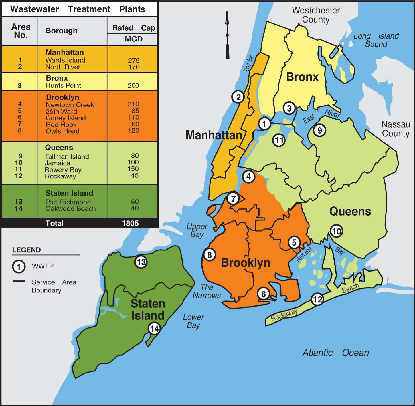
The study area is located in the Queens borough of New York City. The service area for the Jamaica WWTP is denoted as area number 10 in Figure 1, and is comprised of 10,328 ha (25,521 ac). Approximately 21% (2,167 ha) of the total area is serviced by combined sewers, 8% (841 ha) transports runoff directly into nearby water bodies (direct drainage), and 71% (7,308 ha) is serviced by separate storm and sanitary sewers. In total, the area is serviced by 340 km (211 mi) of combined sewers, 824 km (512 mi) of sanitary sewers, and 319 km (198 mi) of storm sewers.
The Jamaica WWTP service area is highly urbanized and contains a large percentage of impervious surfaces. Runoff from roof drains, street gutters, and catch basins are tied into the combined sewer system, generating rapid and intense flow peaks in excess of the Jamaica WWTP capacity, even though New York City WWTPs were generally designed to process higher flows during wet weather. Flow regulators in the combined sewer system limit the amount of flow to the interceptor sewer and divert excess flow to nearby water bodies via outfall lines when the hydraulic capacity of the interceptor system is exceeded. Because the City is situated on the coast, most of the regulator structures have tide gates associated with them to prevent receiving waters from infiltrating the sewer system. Diversion chambers often exist in conjunction with regulators to divert excessive flows to outfalls and subsequently to receiving waters.
Interceptors convey regulated flow from the CSO regulators and connecting branch interceptors to the WWTP. The Jamaica WWTP receives its wastewater from two interceptors: East and West Interceptors. The West Interceptor collects dry weather and some wet weather flow from various CSO Regulators (including JA-3 and JA-14) and is 1.83 meters (72 inches) in diameter. The East interceptor collects dry weather and some wet weather flow various CSO Regulators (including JA-6) and is 2.34 meters (92 inches) in diameter. The West Interceptor serves the drainage area west of the Van Wyck Expressway, which is mostly combined sewer service while the East Interceptor serves the drainage area east of the Van Wyck Expressway (Interstate I-678), an area of mostly separate sanitary sewers.
A typical regulator structure consists of three chambers; a diversion chamber, a regulator chamber, and a tidal or outfall chamber. During dry weather, flow from the combined sewer enters the diversion chamber, where flow is diverted to the regulator chamber passing through a sluice gate. Flow is then conveyed to the interceptor through a branch interceptor connection. Most of the sluice gates in the regulator system have actuators for operation and remote monitoring. Wet weather flow in excess of the regulator's hydraulic capacity passes over the diversion overflow weir, through the tidal chamber and discharges to the outfall causing a CSO event. Tide gates are flap gates that open downstream to permit relief of wet weather flows. The gates are closed by downstream tide levels to prevent inflow to the regulator chamber and ultimately to the plant. Gates are constructed either of timber or cast iron.
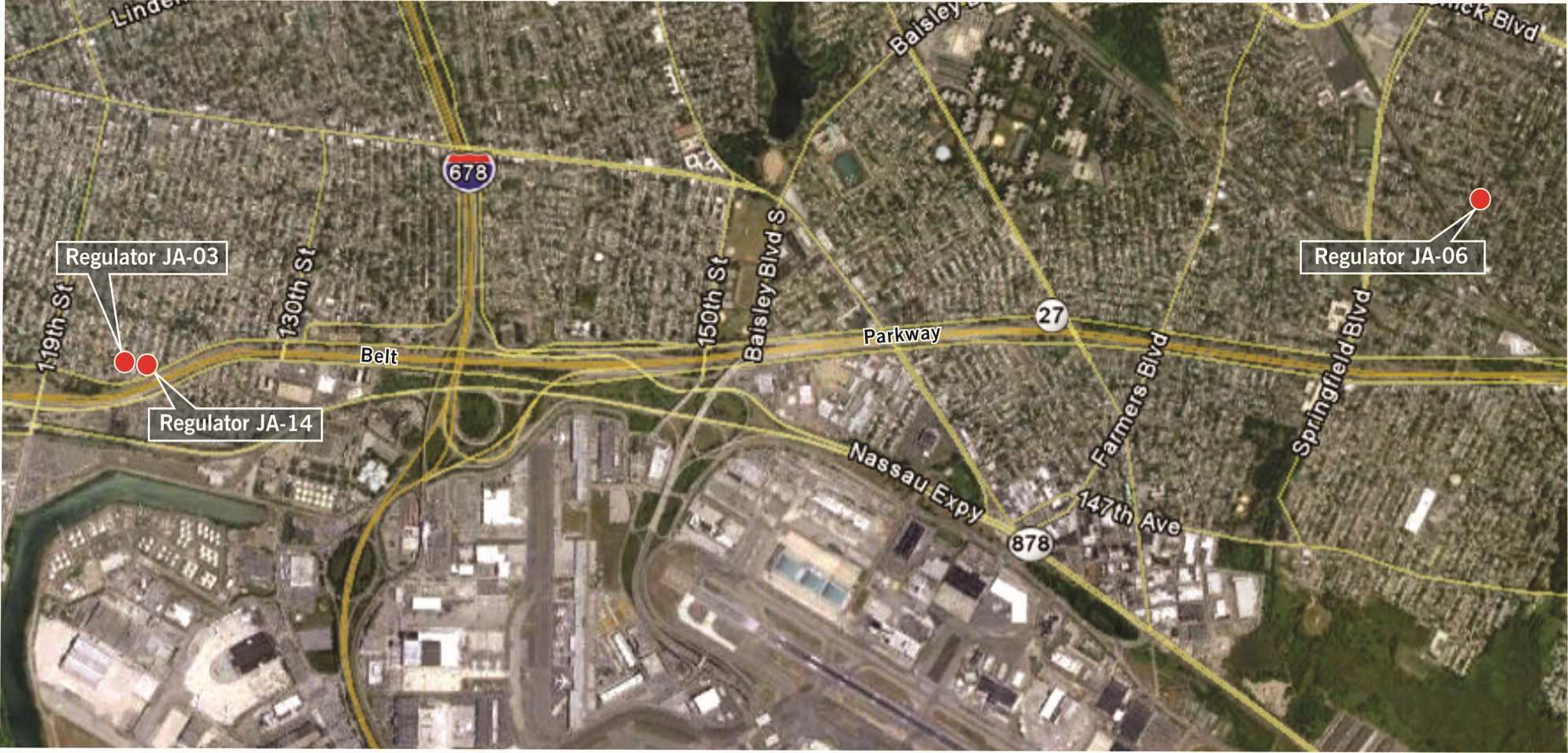
Regulator JA-3 is located at the intersection of 123rd street and 150th Avenue in the South Ozone Park section of Queens. Regulator JA-14 is within one block of Regulator JA-3 at 124th street and North Conduit Avenue. These regulators serve the combined sewer area west of the Van Wyck Expressway. Regulator JA-6 is located at the intersection of 225th Street and 138th Avenue and serves the combined sewer area near Thurston Basin. See Figure 2 for an aerial plan showing the location of these regulators in the service area.
Bending Weir Benefits and Description of Technology
InfoWorks hydrologic/hydraulic sewer system models were developed, calibrated and validated using flow monitoring and rainfall data collected throughout the City’s sewer system and used to develop alternatives for CSO reduction. The output from the InfoWorks models are used as loadings into various receiving water quality models that were developed in parallel to demonstrate in-stream water quality standard attainment.
The existing system has conveyance limitations in the West Interceptor and relatively low weir crest elevations that result in CSO discharges occurring before significant surcharging and buildup of driving head in the downstream interceptor can occur. Based on InfoWorks model simulations, an analysis determined that, in addition to a parallel 1.22-meter (48-inch) diameter sewer across the Belt Parkway to relieve a local system bottleneck, regulator modifications at Regulators JA-3, JA-14 and JA-6 will provide CSO reduction benefits. The additional capacity provided by increasing the hydraulic head at regulator structures JA-3 and JA-14 utilizing bending weirs will convey more flow across the Belt Parkway and thereby reduce the amount of CSO discharging into Bergen Basin. The bending weir at Regulator JA-6 will also increase the hydraulic head in the downstream sewers, better utilizing in-system capacity and reducing CSO discharges to Thurston Basin. Modeling indicates that, during a typical annual average rainfall condition, CSO volumes to Bergen and Thurston Basin could be reduced by 643,450 m3 (170 million gallons) per year by implementing bending weirs alone.
Bending weirs are passive devices that are designed to maximize upstream in-system storage and capacity for smaller and medium-sized storms, while allowing flows generated during larger storm events to discharge in a similar manner as they do without the bending weirs.
Conversely, while increasing the fixed weir height of a regulator will also increase storage capacity, it will reduce the discharge capacity of the regulators during large events. Thus, bending weirs were selected to accomplish the dual goal of reducing CSOs during more frequent storms, and maintaining current flow capacity at the outfalls during larger storms.
In general, the following features and benefits are common to many, if not all types of bending weirs:
- Maximize in-system storage
- Reduce CSO discharges, both in frequency and volume
- Improved weir coefficient compared to a fixed weir
- Stainless steel construction to ensure longevity in a sewerage environment
- Reduced capital costs compared to other CSO reduction strategies, including pipe upsizing, sewer separation, retention tanks or treatment facilities
- Low maintenance
- Customizable factory equipment for easy drop-in installations
While there are at least four types of bending weirs in existence, the overtopping counterweighted type was selected for this application. The design of the flap incorporates a relationship between the fixed and dynamic hydraulic forces and the design of the eccentric control disc balancing the counterweight arrangement. The flap, in its up or resting position, holds back the rising water until the flow reaches the design set point level. When the activation level is reached, the weight of water will overcome the counterweights - lowering the flap and releasing the overflow downstream. The flap will continue bending as the water level rises until it meets the bottom stop strip and prevents the unit from exceeding its bending limits. In the fully open (down) position, the equipment is flush with the fixed weir level. When the water level recedes, the flap will automatically return to the upright resting position. In the fully open position, the equipment allows flows which will either exceed or at least be equivalent to those of a fixed weir.
The flap is constructed from stainless steel with stiffeners connected to a solid stainless steel shaft. Stainless steel side plates include preformed stops that match the flap’s contoured shape and seal the openings when the unit is in its resting, upright position. The shaft is attached to a counterweight assembly which can either be mounted downstream in the sewer or within a separate dry compartment that is not exposed to the sewer flows, the latter of which is the preferred option. Although the equipment is factory tested and balanced it can be field-adjusted as well by adding or removing weights.
This equipment is customizable based on length and height to address specific overflow rates. The fixed weir may have to be either raised or lowered to optimize the equipment selection to achieve the design flow rate for a specific site. The equipment requires sufficient height on the downstream side of the fixed weir for anchoring the flap. The practical minimum fixed weir height is 12 inches. The equipment also requires space for the unit to be in the fully open down position which corresponds with the unit height.
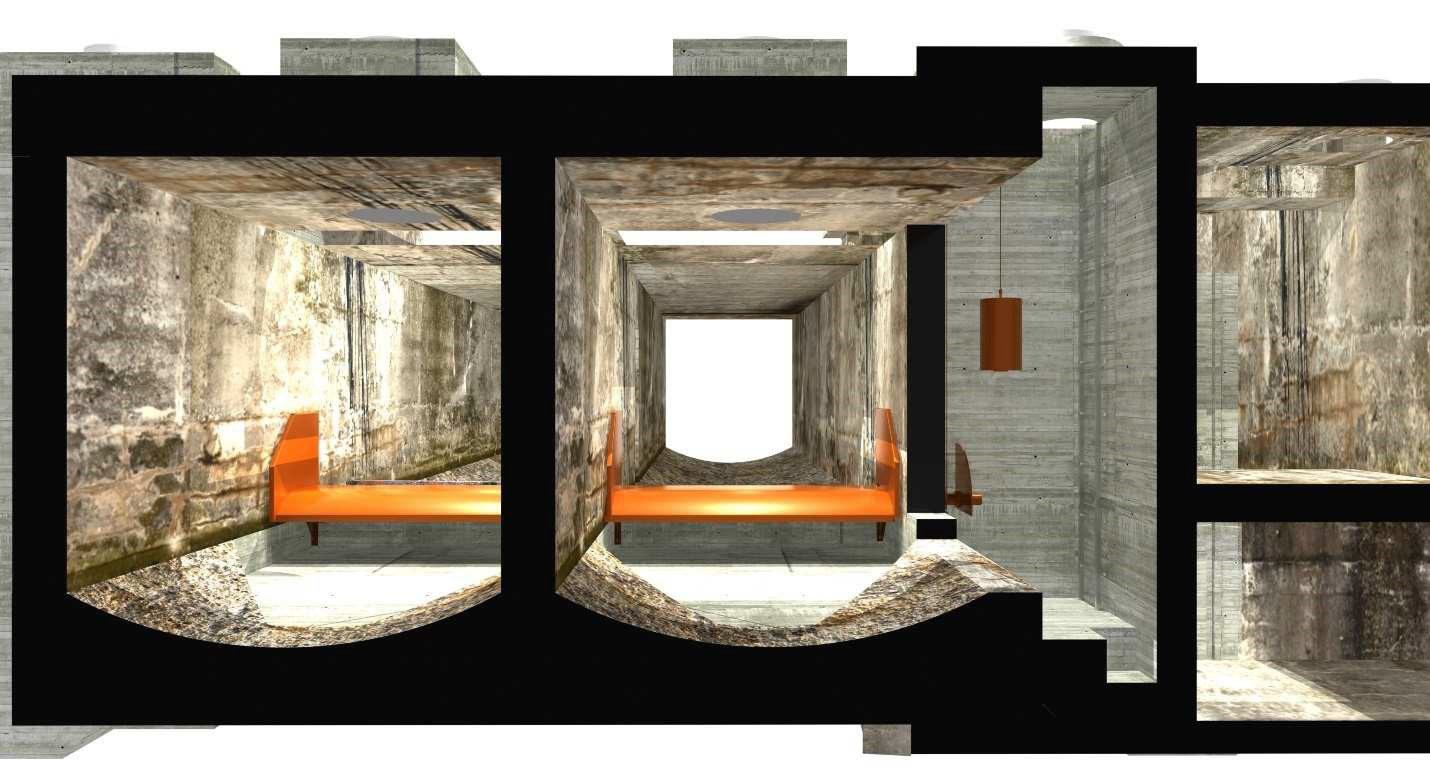
Figure 3: 3D CAD Rendering of Regulator JA-3
Figure 3 illustrates a 3D CAD rendering of the existing Regulator JA-3, which includes a double-barrel influent/effluent configuration. The bending weirs are shown in orange color, and are displayed in the fully open (down) position. Flow enters the regulator from the background, and then is normally conveyed to the right into the West Interceptor en route to the WWTP. If wet weather flows overwhelm the system then a CSO can occur, with flow traveling towards the foreground and into Bergen Basin. The counterweight chamber is also shown to the right of the bending weirs.
Summary and Conclusions
The regulator modifications at JA-3, JA-14 and JA-6 will achieve the following objectives:
- Increase the height of the effective overflow elevation in Regulators JA-3, JA-14 and JA- 6 by 0.61 meters (2 feet). Increasing the effective overflow elevation in the diversion area by this amount results in a reduction of CSO events and volume compared to the existing hydraulic conditions. Increasing the effective overflow elevation will allow for increased storage in the collection system to minimize the frequency of overflows.
- Maintain the current hydraulic capacity in the interceptor system during significant wet weather events. Modifications to the overflow elevation in Regulators JA-3, JA-6 and JA-14 must not adversely impact the users upstream of the regulators.
- Increase the hydraulic capacity at Regulator JA-3 at the orifice (i.e., wall opening) between the diversion area and regulator chamber. Currently, the hydraulic capacity is limited by existing sluice gate installed in the common wall between the regulator chamber and the diversion area. Enlargement of this wall opening will accomplish this objective.
To reiterate, while bending weirs are passive devices that are designed to maximize upstream in- system storage and capacity for smaller and medium-sized storms, they also allow flows generated during larger storm events to discharge in a similar manner as they do without the bending weirs. Conversely, while increasing the fixed weir height of a regulator will also increase storage capacity, it will reduce the discharge capacity of the regulators during large events. Therefore, bending weirs were selected to accomplish the dual goal of reducing CSOs during more frequent storms, and maintaining current flow capacity at the outfalls during larger storms. By implementing bending weirs alone, during typical annual average rainfall, CSO volumes to Bergen and Thurston Basin could be reduced by 643,450 m3 (170 million gallons) per year.