Big Bubble Mixing Enhances BNR Performance in a Unique Modified Four-Stage Facility
Last Modified Feb 07, 2022
The City of Orlando (city) completed facility improvements in February 2016 at the Water Conserv II Water Reclamation Facility (WCIIWRF) that enhanced the biological nutrient removal (BNR) within the facility basins. The key goal of the improvements was to provide mixing within the first anoxic basins to reduce dissolved oxygen concentrations and enhance denitrification.
The city wished to maximize the capacity and treatment capabilities within the BNR process. Prior to the project, mixing of the anoxic zones was accomplished through the addition of a low level of diffused air. A similar level of low aeration is used within the “second anoxic” zones within aeration basins 5-10; however, it was determined that even low levels of air increased the dissolved oxygen (DO) level enough to impact denitrification within the basins. To improve mixing within the basins and reduce DO levels, two alternatives were proposed: hyperboloid mixers and big bubble mixing technology, both of which have been used in the municipal wastewater industry. The purpose of the project was to evaluate both technologies on performance and net-present-worth comparisons.
The city owns and operates WCIIWRF. The 21-mil-gal-per-day (mgd) annual average daily flow (AADF) facility consists of flow equalization, preliminary treatment, biological nutrient removal (BNR), clarification, dual media filters, and disinfection. Solids handling includes thickening, a proprietary lime stabilization process, and dewatering.
Related Solutions:
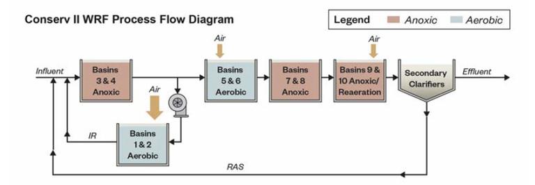
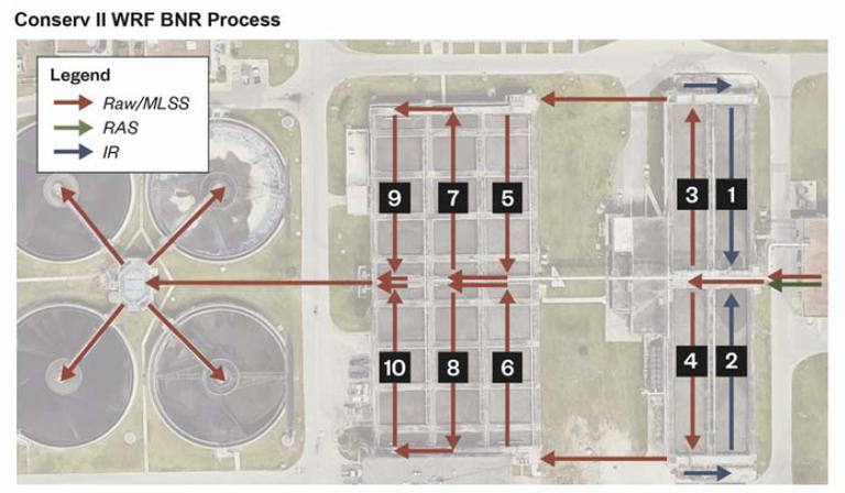
Biological Nutrient Removal Schematic
The BNR process consists of two trains: the north train consists of basins 1, 3, 5, 7, and 9, while the south train consists of basins 2, 4, 6, 8, and 10. The ten basins are located in two sets of consecutive rectangular tanks: basins 1-4 are located in the first tank and basins 5-10 are located in the subsequent tank.
The improvements redirected the flow path within basins 1-4 and constructed a mixing system for basins 3 and 4. Prior to the project, a low flow of diffused aeration was used to provide mixing within the anoxic basins; however, the small amount of aeration resulted in suboptimal performance. The redirection of the internal recycle flow from basins 3 and 4 to basins 1 and 2 allowed for the process to use the basins with the highest fine bubble diffuser density for aerobic zones.
The current flow path sends influent flow, return activated sludge (RAS), and internal recycle (IR) through the anoxic zones in basins 3 and 4. The IR pumps deliver approximately two times the influent flow from the effluent channel of basins 3 and 4 over the wall and into basins 1 and 2 where it flows in the reverse direction. Basins 1 and 2 aerate the IR with high-efficiency diffusers flow going to basins 3 and 4. After these four basins, the flow continues to basins 5-10, where it flows in a serpentine pattern.
A portion of basins 5-10 is maintained with minimum aeration to create a "secondary anoxic zone." The facility uses online nutrient monitoring to adjust performance parameters within the basins, such as airflow and IR.
Design Comparison
The hyperboloid-style mixer installation requires modifications to each of the basins to accommodate hanging the mixer in the center of each basin. At basins 3 and 4, new fabricated aluminum structures could be provided to support the new mixers; at basins 7, 8, 9 and 10, the existing walkways would require modifications to the concrete infrastructure to support the mixers. Additionally, existing concrete columns supporting the walkway create constraints on mixer locations.
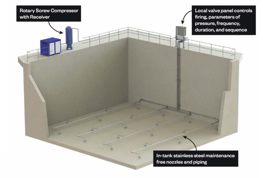
For this installation, big bubble mixing can provide adequate mixing for solids suspension, with a reduction in power consumption compared to hyperboloid mixers. In addition to potential energy savings, use of the big bubble mixing system requires less structural modifications to the basins for access. All moving parts of the big bubble mixing system, including the compressor and air control valving, are installed above the water line, facilitating maintenance.
Three 200-pounds-per-sq-in. (psi) air compressors (two active and one standby) are required as part of the big bubble mixing package for all six basins. A phased design of installing basins 3 and 4 now and basins 7-10 later requires only two compressors, with one serving as active and one as standby.
Life Cycle Analysis
To provide the city with an equal basis for deciding between the hyperboloid mixers and big bubble mixers, costs were evaluated on a life cycle analysis. For each type of mixer, the capital, electrical, and maintenance costs were included. Each mixer type required modifications to the existing fine bubble tube diffusers to pin them to the basin floor or provide a clear space around the mixer.
Additionally, the hyperboloid mixers required that aluminum walkways be constructed to support the mixers within the center of the basin, and the big bubble mixers included a pre-engineered steel building construct above the compressors.
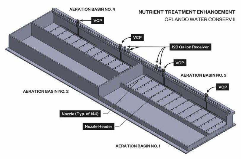
Big Bubble Design Description
Based on the life cycle analysis, the city decided to move forward with final design and bidding of the big bubble mixing system.
For basins 3 and 4, there are 12 nozzle headers in each basin. Each header has six nozzles, for a total of 72 nozzles in each basin. Each basin has two VCPs, each with six valves, which supply air to the headers. Each VCP has a dedicated receiver tank located adjacent to the panel that keeps the system pressurized. Two compressors (one duty and one standby) are located adjacent to the aeration tanks, and are housed under a new canopy structure for protection of equipment and staff during maintenance. Due to ease of installation, press-fit stainless steel piping was utilized for the mixing system air piping. The master control panel is located in an adjacent electrical room and contains the control screen, with various parameters that can be adjusted, including pressure (25-30 psi), valve firing frequency, valve firing duration, and valve firing sequence. The parameters allow the operators to fine-tune the system and can provide operational flexibility; if desired, a portion of the system could be kept in mixing mode while another portion is aerated. Mixing and aeration can also be operated simultaneously, if desired.
Conclusions
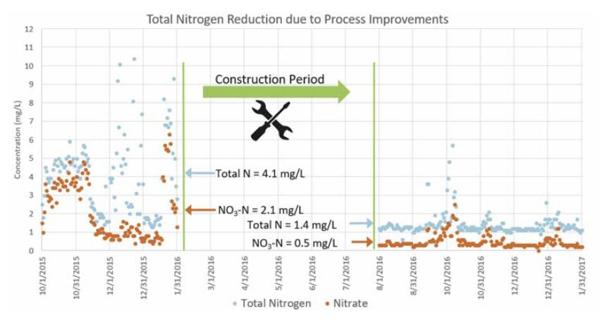
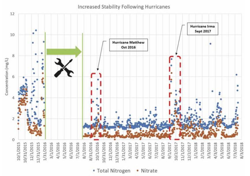
This successful project for the city resulted in construction of an energy-efficient mixing system, with low maintenance for the city. The mixing system enhanced denitrification within the biological process and improved overall plant performance. The facility consistently achieves effluent total nitrogen (TN) concentrations well below what is typically accepted as the limit of technology (TN<3 mg/L). In addition to the mixing system, the combination of mixing and aeration in the same tank and the unique internal recycle flow scheme allows the facility to maximize flexibility and allows for basins to be taken offline without significantly impacting plant performance.
Not only has effluent quality improved since the project, but ease of operation has also improved. The biological system was enhanced because of the increased mixing and the use of true anoxic basins. In addition to improving overall effluent quality and providing for operational flexibility of the BNR process, installation of the mixing system appears to have improved the time for the facility to recover following high-flow events, such as hurricanes. The big bubble mixing system improved plant resiliency and allowed for a quicker recovery of effluent quality following the high inflow.
Based on the increase in facility performance from the successful project, the city has decided to move forward and expand the remainder of the big bubble mixing system in Basins 7-10.
This article is excerpted from the October 2018 issue of the Florida Water Resources Journal.